HV Generator
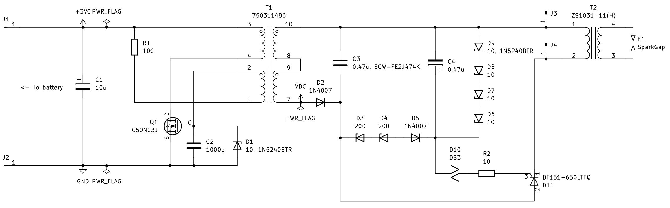
The circuit consists of 2 parts: Oscillator (T1 primary) and step-up (T1 secondary).
The oscillator is described in detail below. In summary, it charges C3 to 430 V, then discharges across T2 for the final 30 kV arc.
D1 protects MOSFET Q1 from high voltage pulses, D6-D9 clamps the maximum voltage on C3 and C4 to 440 V and 40 V respectively, R2 limits the current to SCR D11 when C4 discharges.
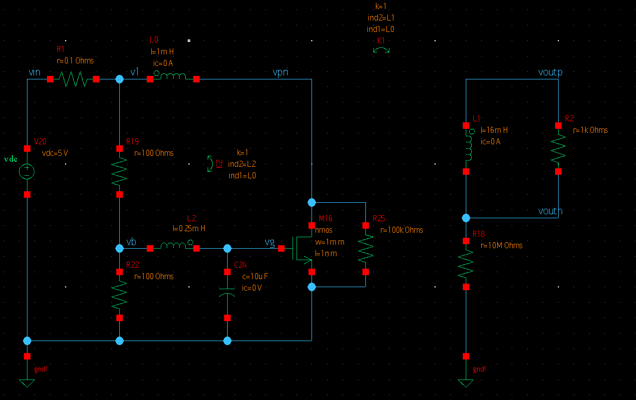
Circuit model for simulation is shown on the left. L0 and L2 are coupled to provide positive feedback.
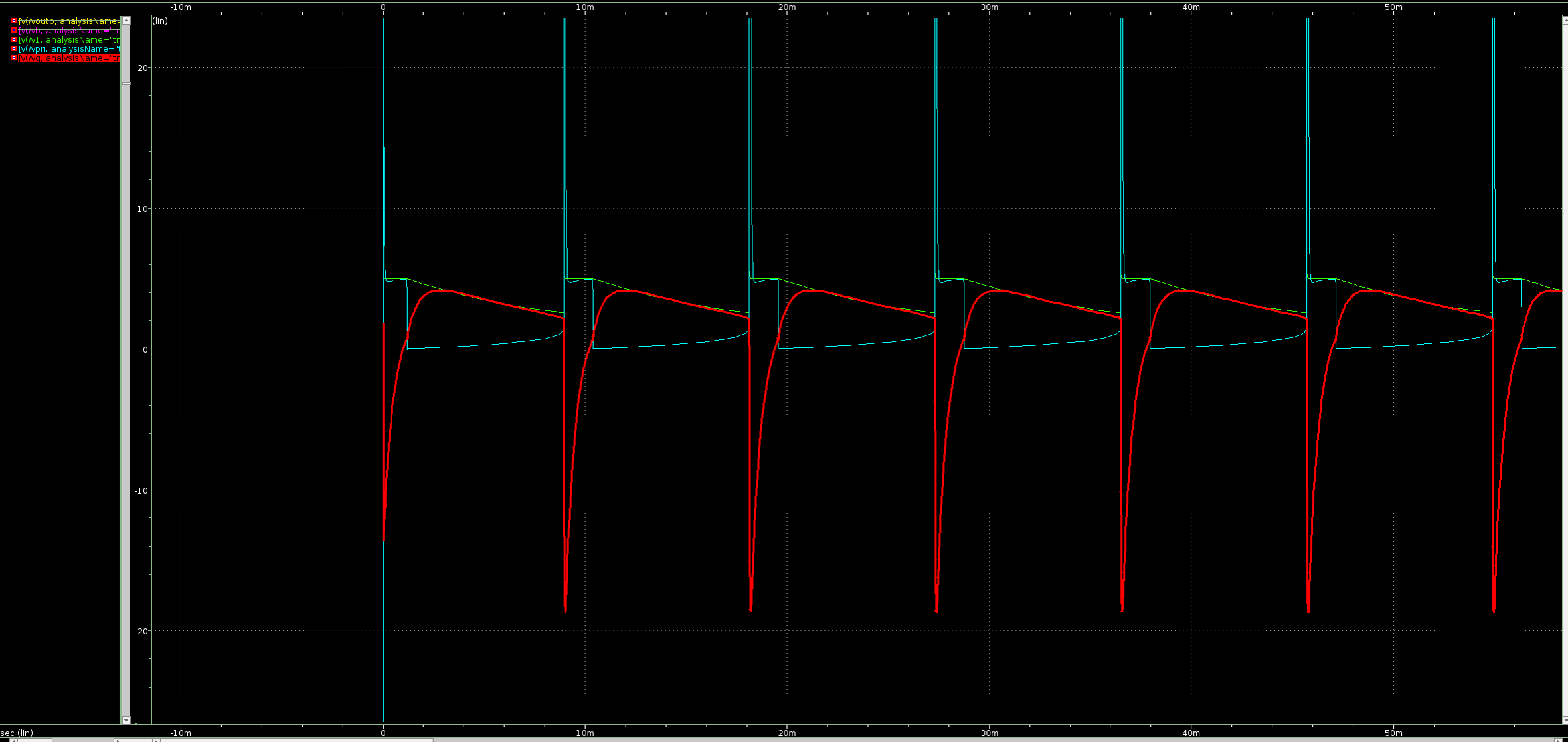
Initially MOSFET conducts and L0 is charging, positive feedback increases gate voltage vg (red) to further increase current. As current increases, IR drop decreases v1 (green) and vg falls. At t=18 ms L0 discharges to maintain current, positive feedback decreases vg, further decreasing current - producing the vpri spike (blue).